
MATLAB | NoLimits | CFD | FEA
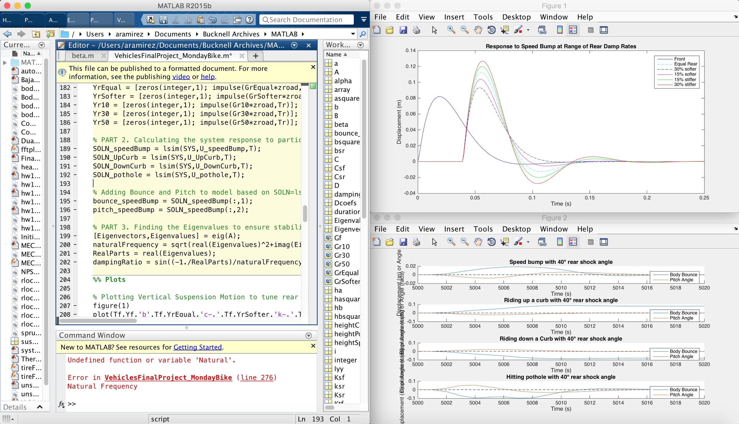
I designed and simulated a suspension system for the M1 electric motorbike in MATLAB that would allow it to conquer obstacles with the ease of a dirt bike while maintaining the smooth, refined ride of a road bike.
I simulated a mono-shock rear suspension design by creating a mathematical model in MATLAB based on the coupled equations of motion and bounce and pitch dynamics. I assumed a fixed front fork angle and pre-defined displacements taken from average road condition data (speed bumps, potholes, curbs, etc.). I then varied shock stiffnesses and rear shock angle to determine the optimal setup for the suspension. The simulation takes into account the bounce, pitch, and oscillation stability of the suspension setup and outputs it in graphical form.
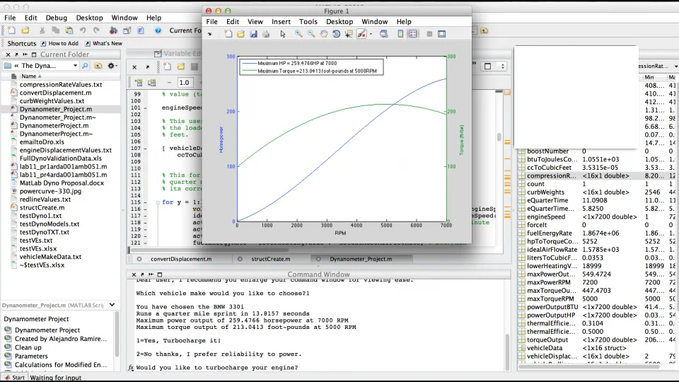
Most companies only report data such as horsepower, torque, engine displacement, and a number of other max value data about their cars. I wanted to develop a model that could help predict performance characteristics of specific cars across the power band without having to physically run the car on a dynamometer.
I developed an algorithm in MatLAB that interacts with the user and pulls vehicle data from the web to create a simulated dynamometer. The code prompts the user to select a make and model of vehicle, then pulls manufacturers data to make a series of performance calculations on the specific vehicle and output results in the form of tables and figures (including torque speed curves, max power, air and fuel flow rates, etc.)
This project allowed me to learn how to design an algorithm using engineering knowledge to create a simplified mathematical model of a complex process. I got an introduction to structures in MATLAB and further experience with writing functions, plots, for loops, if statements, and user prompts. I also gained an understanding of how to validate your analysis with external resources, in this case published car data, to ensure that your model was as accurate as advertised (and understanding why there are some discrepancies from a technical perspective).
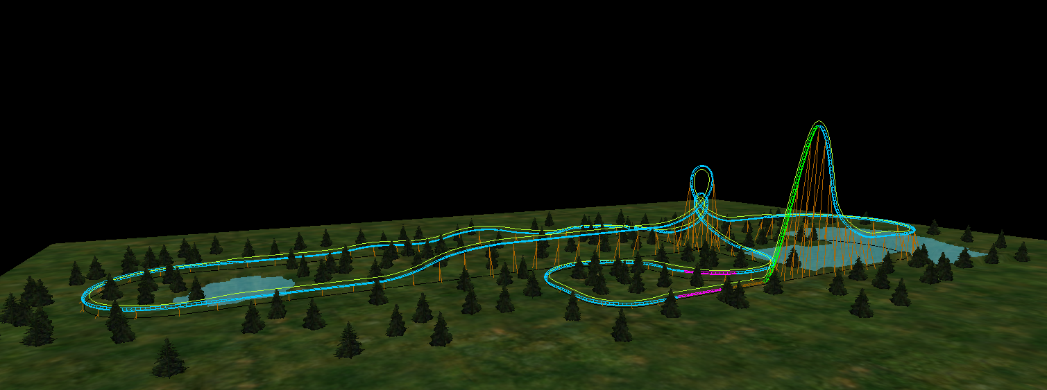
This project charged our three-man team with using the principles of engineering dynamics to design a roller coaster in the NoLimits software using technical calculations and simulations. The roller coaster came to fruition through several collaborative design discussions and was driven by engineering calculations from conception.
We used principles of dynamics to determine velocity and radius of curvature at various points based on height, pitch angle, and desired acceleration, and used a kinetic energy equation (neglecting frictional losses) to predict velocities along the length of the coaster. Design constraints were focused primarily on cost and rider-experienced g-forces, ensuring a final product that could be viable for market. All of the preliminary calculations were fed into the NoLimits software, which used bezier curves to build coaster geometry. Once defined, the simulation ran full-speed simulations and performed calculations that closely matched our predicted values. A more detailed explanation of the process was documented in a memorandum.
This project allowed me to apply the principles of dynamics to a real world design project, particularly related to accelerating bodies and transient structural loading. I developed my interpersonal skills by working on a long-term project with other Mechanical Engineering students. It also gave me experience working on a highly technical team to take on new challenges beyond the scope of the project, such as modeling and calculating parameters, ODEs, and Bezier curves for an inverted loop feature in a software that I had to teach myself (NoLimits).
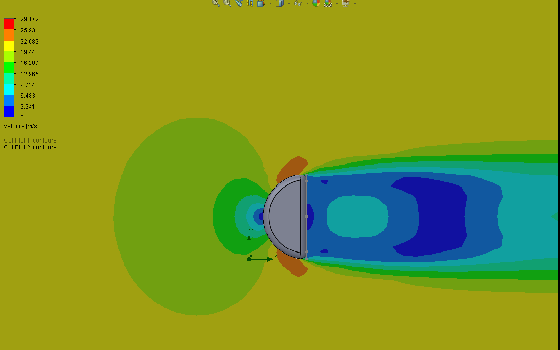
This was a project for a Fluid Dynamics course where we were tasked with designing a low-drag side-view mirror for an automobile. Using a combination of automotive design inspiration and fluid dynamics knowledge, I began creating my model in SolidWorks. After designing the 3D model, I used the SolidWorks computational fluid dynamics flow simulation add-on to analyze my design. Next, I used our university Makers Space to 3D print a prototype of my mirror for real-time performance testing in a wind tunnel. I used LabVIEW to collect data from custom-built pressure sensors, pitot tubes, and digital anemometers. I then compared these experimental results to the theoretical results in order to suggest improvements to the overall design.
This project was a great opportunity to learn about creating and validating CFD analysis software on 3D models in SolidWorks. It reinforced the importance of rapid prototyping, and gave me experience testing designs in a wind tunnel and collecting real-time experimental data from a test cell for analysis. I then developed my ability to compare experimental and theoretical results and communicate agreements and discrepancies using technical reasoning.
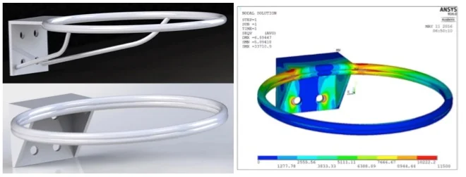
This project focused on redesigning the local playgrounds basketball hoop using finite element analysis. The aluminum basketball rim was modeled in SolidWorks, imported into ANSYS Mechanical as an .IGES, and analyzed using several static mechanical loading conditions.The geometry of the part was created in SolidWorks using extruded, revolved, and swept boss features. All volumes were merged using the combine feature to ensure translation into ANSYS for finite element analysis.
The new design was tested under four different loading conditions with constant boundary conditions. After considering stress discontinuities and validating my assumptions, the finite element model supported the benefits of investing in the new design for longer-term performance.